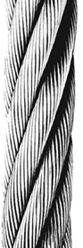
With precise, moving parts, designed and manufactured to bear definite relationship to one another, wire rope can be a complex mechanism.
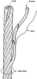
Wire rope is generally composed of wires, strands, and the core (See Fig.). The wires are helically laid together in a precise geometric pattern to form the strand. The strands are laid about the core to form the wire rope. The process of positioning the strands
about the core is called “closing.” The process of positioning the wires within the strand is called “stranding.”
Wire rope varies by:
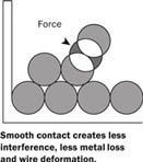
The RIGHT Way

The WRONG Way
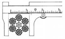
The first differentiation of wire rope is by diameter. Generally, a new wire rope is manufactured to its nominal diameter + 2 ½%. This allows for the normal reduction of diameter experienced when a new rope is placed under load.
The grade of steel utilized in the construction of the wire rope has a major influence upon the ultimate break strength. Most steel wire rope today is Extra Improved Plow Steel Grade (EIPS).
Manufacturers have begun producing limited constructions of Extra Extra Improved Plow Steel (EEIPS), which are 10%-15% higher than similar EIPS grade ropes. Some special constructions exceed EEIPS grade.
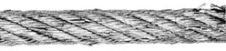
The “Lay” of the wire rope (the direction of stranding and closing) directly affects the operating properties. In Regular Lay wire rope, the direction of the wires are twisted in an opposite direction than the direction of the strands. Regular Lay may be Right Regular Lay or Left Regular Lay depending upon the direction of the strands. (Fig. 1)
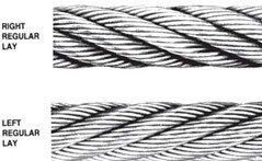
Fig. 1
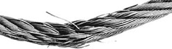
In Lang Lay wire ropes the direction of the wires are twisted in the same direction as the strands. Lang Lay may be Right Lang Lay or Left Lang Lay depending upon the direction of the strands. (Fig 2)
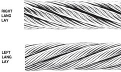
Fig. 2
The wires of a Regular Lay wire rope travel parallel and along the length of the rope while those of a Lang Lay rope travel parallel to the axis of the strand.
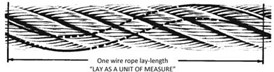
In addition, the rope lay length (distance required for one strand to travel 360o around the core) can vary slightly among manufacturers.
The most widely used wire rope replacement, inspection and maintenance standard for mobile-type cranes is ASME B30.5, section 5-2.4. The following is an excerpt from that standard.
All running ropes in service should be visually inspected once each working day. A visual inspection shall consist of observation of all rope which can reasonably be expected to be in use during the day’s operations. These visual observations should be concerned with discovering gross damage, such as listed below which may be an immediate hazard:
The frequency of detailed and thorough inspections should be determined by a qualified person, who takes into account the following factors:
Inspect the entire length of the rope. Some areas of the wire rope such as around the core are more difficult to inspect.
To inspect the core, examine the rope as it passes over the sheaves. The strands have a tendency to open up slightly which will afford the inspector a better view of the core. Also regularly inspect for any reduction in diameter and lengthening of rope lay as both conditions indicate core damage.
Abrasion – Abrasion damage may occur when the rope contacts an abrasive medium or simply when it passes over the drum and sheaves. Therefore it is vital that
all components be in proper working order and of the appropriate diameter of the rope. A badly corrugated or worn sheave or drum will seriously damage a new rope, resulting in premature rope replacement.
Corrosion – Corrosion is very difficult to evaluate but is a more serious cause of degradation than abrasion. Usually signifying a lack of lubrication, corrosion will often occur internally before there is any visible external evidence on the rope’s surface. A slight discoloration caused by rusting usually indicates a need for lubrication which should be tended to immediately. If this condition persists, it will lead to severe corrosion which promotes premature fatigue failures in the wires and strands, necessitating the rope’s immediate removal from service.
Wire Breaks – The table below shows the number of allowable wire breaks per crane type. The inspector must know the ASME standard for the equipment being inspected. The number of broken wires on the outside of the wire rope is an indication of its general condition and
whether or not it must be considered for replacement. The inspector may use a type of spike to gently probe the strands for any wire breaks that do not protrude. Check as the
rope runs at a slow speed over the sheaves, where crown (surface) wire breaks may be easier to see. Also examine the rope near the end connections. Keeping a detailed inspection record of the wire breaks and other types of damage will help the inspector determine the elapsed time between breaks. Note the area of the breaks and carefully inspect these areas in the future. Replace the rope when the wire breaks reach the total number allowable by ASME or other applicable specifications.
Other than the applications listed above, valley breaks or breaks in between strands, must be taken very seriously at all times! When two or more valley breaks are found in one lay-length, immediately replace the rope.
TENSION BREAK
Wire break shows one end of broken wire coned, the other cupped. Necking down of the broken ends is typical of this type break. Where tension breaks are found, the rope has been subjected to overloading, either for its original strength (new rope) or for its remaining strength in the case of a used rope. Tension breaks are frequently caused by the sudden application of a load to a slack rope, thereby setting up incalculable impact stress.


ABRASION BREAK
Wire break shows broken ends worn to a knife-edge thinness. Abrasive wear is obviously concentrated at points where the rope contacts an abrasive medium, such as the grooves of sheaves and drums or other objects with which the rope comes into contact. Unwarranted abrasive wear indicates improperly grooved sheaves and drums, incorrect fleet angle, or other localized abrasive conditions.

FATIGUE BREAK
Wire breaks are usually transverse or square showing granular structure. Often these breaks will develop a shattered or jagged fracture, depending on the type of operation. Where fatigue breaks occur, the rope has repeatedly been bent around too small a radius. Whipping, vibration, slapping, and torsional stresses will also cause fatigue. Fatigue breaks are accelerated by abrasion and nicking.


CORROSION BREAK
Easily noted by the wire’s pitted surface, wire breaks usually show evidence of tension, abrasion, and/or fatigue. Corrosion usually indicates improper lubrication. The extent of the damage to the interior of the rope is extremely difficult to determine; consequently corrosion is one of the most dangerous causes of rope deterioration.

CUT OR SHEAR
Wire will be pinched down and cut at broken ends or will show evidence of shear-like cut. This condition is
evidence of mechanical abuse caused by agents outside the installation, or by something abnormal on the installation itself, such as a broken flange.

ABRASION
CORE PROTRUSION & SLIPPAGE
CORROSION
CRUSHING
![]()
DIAMETER REDUCTION
Core Protrusion (Shockloading)
Corrosion
HIGH STRANDING
JUMPING THE SHEAVE
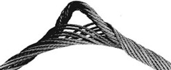
KINKING
LAY LENGTHENING & TIGHTENING
LOOPED WIRES
UNBALANCED ROPE
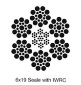
Strands: 6
Wires per strand: 19 to 26 Core: IWRC or Fiber Core Standard Grade: EIPS Lay: Regular or Lang Finish: Bright or Galvanized
The 6×19 classification of wire rope is the most widely used. With its good combination of flexibility and wear resistance, rope in this class can be suited to the specific needs of diverse kinds of machinery and equipment.
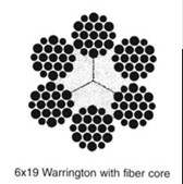
The 6×19 Seale construction, with its large outer wires, provides great ruggedness and resistance to abrasion and crushing. However, its resistance to fatigue is somewhat less than that offered by a 6×25 construction.
The 6×25 possesses the best combination of flexibility and wear resistance in the 6×19 class due to the filler wires providing support and imparting stability to the strand. The 6×26 Warrington Seale construction has high resistance to crushing. This construction is a good choice where the end user needs the wear resistance of a 6×19 class rope and the flexibility midway between a 6×19 class and 6×37 class rope.

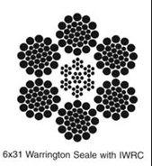
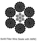
Strands: 6
Wires per strand: 27 to 49 Core: IWRC or Fiber Core Standard Grade: EIPS Lay: Regular or Lang Finish: Bright or Galvanized
The 6×36 class of wire rope is characterized by the relatively large number of wires used in each strand. Ropes of this class are among the most flexible available due to the greater number of wires per strand, however their resistance to abrasion is less than ropes in the 6×19 class.

The designation 6×36 is only nominal, as in the case with the 6×19 class. The ropes may not actually have 36 wires per strand. Improvements in wire rope design, as well as changing machine designs, have resulted in the use of strands with widely varying numbers of wires and a smaller number of available constructions.
Typical 6×36 class constructions include 6×33 for diameters under 1/2”, 6×36 Warrington Seale (the most common 6×36 class construction) offered in diameters 1/2” through 1-5/8”, and 6×49 Filler Wire Seale over 1-3/4” diameter.
6 x 19 Class
6×19 Seal
6×19 Warrington
6×21 Filler Wire 6×21 Seale
6×25 Filler Wire 6×25 Seale
6×26 Warrington Seale
6 x 36 Class
6×31 Warrington Seale
6×33 Warrington Seale 6×36 Warrington Seale
6×41 Warrington Seale
6×43 Filler Wire Seale
6×49 Filler Wire Seale
NOTE:
Technical data for the above listed constructions are the same and detailed in the table. For further information on additional constructions and diameters, contact your ALP Sales Representative.
In certain instances the use of rotation-resistant wire rope is necessary to provide rotational stability to the lifted load. In general, the use of these wire ropes is limited to those situations where it is impractical to:
Rotation-resistant wire ropes have less of a tendency to unlay when loaded than do conventional wire ropes.
This results in improved rotational stability to the lifted load. Rotation-resistant wire ropes are designed in such a way that the rotational force of the outer strands
is partially counteracted by the rotational force of the inner strands or core when the rope is subjected to a load.
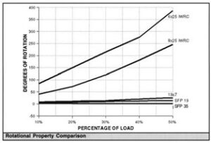
The chart compares the rotational properties of rotation-resistant ropes with a standard 6×25 wire rope. The rotation-resistant ropes far surpass the rotational stability of a conventional 6×25 IWRC wire rope on both short and long falls.
ASME B30.5 specifies that rotation-resistant ropes have a safety design factor of five or greater. The required strength design factor of rotation-resistant rope becomes very important from the standpoint of maintaining the inherent low rotation of the rope and eliminating any tendency to overload the inner core, thereby causing a reduction in rope strength.
Precautions should be followed when using rotation-resistant wire rope. The rope ends must be properly seized and secured (refer to “Handling and Installation: Seizing Wire Rope”) and cut with a saw or impact hammer to prevent unlaying of the strands.
Attachment of end fittings must be done with care to prevent kinking or unlaying of rope, which harms the balance of the rope.
Operation of rotation-resistant wire ropes (excluding SFP 35™) with a swivel is generally not recommended. The use of a swivel allows the inner core to twist tighter, resulting in a significant reduction in rope strength, possibly leading to premature rope failure. A swivel may be used as a temporary device only during the initial installation period to help eliminate any installation-induced twisting or cabling.
The swivel must be removed from the reeving after the rope installation is completed and before the crane begins operation.
Due to the opposite lay direction of the inner core and outer strand layers in rotation-resistant ropes, care should be taken to avoid shock loading. Shock loading will result in distortion of the rope structure, causing bird-caging, core protrusion, etc. Due to the potential for complete rope failure, shock-loaded wire ropes must be immediately removed from service.
CAUTION
The rated strengths of the 19×7 and 8×19 class wire ropes are less than wire ropes in the 6×19 and 6×36 classes.
Larger sheaves are required in order to achieve comparable fatigue life.
For further information on proper sheave sizes, contact your ALP Sales Representative.
19 x 7 Rotation-Resistant

Strands: 19
Wires Per Strand: 7
Core: WSC
Standard Grade(s): EIPS
Lay: Regular
Finish: Bright
19×7 is recommended for hoisting unguided loads with a single-part line.
The rotation-resistant properties of this rope are secured by two layers of strands. The inner strands are left lay, while the 12 outer strands are right lay, which enables one layer to counteract the other layer’s rotation.The rotation-resistant characteristics of the 19×7 wire ropes are superior to those of the 8×19 Class wire ropes.
8 x 19 Rotation-Resistant

Wires Per Strand: 19
Core: IWRC
Standard Grade(s): EIPS
Lay: Regular
Finish: Bright
8×19 is recommended for hoisting unguided loads with a single-part or multi-part line.
The eight outer strands are manufactured in right lay, with the inner strands being left lay.
These ropes are slightly stronger and significantly more rugged than the 19×7 construction. However, the rotation- resistant properties of the 8×19 rotation-resistant ropes are much less than those of the 19×7 construction.
These ropes are manufactured in right regular lay in the 8×19 Seale and 8×25 Filler Wire constructions.
Galvanized


Small diameter galvanized wire rope, sometimes called Galvanized Aircord, has many applications. These include small winches and hoists, overhead doors, yacht rigging, and clothes line. This rope may also be coated with vinyl, plastic, or urethane. When used as an operating rope they should be lubricated.
ALP has both domestic and imported sources for these products.
In some applications, these ropes are required to conform to MIL-DTL-83420.
Stainless (Corrosion Resistant)

Stainless ropes are used in environments which would quickly degrade bright or galvanized ropes. The term “Corrosion Resistant” is technically preferable to “Stainless” because these products are not stainless in all atmospheres. Types 302/304 are offered in all common sizes.
Types 305/316 are available on special order. All operating ropes should be lubricated.
In some applications, these ropes are required to conform to MIL-DTL-83420.


These items will require special order.
ALP stocks many common diameters of small strand products. Strand products generally have constructions like 1×7, 1×19, etc.
Both galvanized and stainless strand products are available. Various grades of strand are available including aircraft quality, common grade, utility grade and EHS. In addition, larger diameter products are available for pendants and support lines.

Strands: 19
Wires Per Strand: 19
Core: WSC
Standard Grade(s): EEIPS
Lay: Right Regular
Finish: Bright
SFP 19 is recommended for both multipart load and single- part fast line applications where rotational stability of the lifted load is needed, such as for use as long fall on offshore pedestal cranes, rough and all terrain cranes, and crawler cranes.
SFP 19 PROVIDES:
Fatigue Resistance Improved fatigue properties are derived through the combination of the flexible 19×19 construction and die drawn strands. The drawn strand surfaces minimize the interstrand and interlayer nicking that take place in round rotation-resistant ropes. Abrasion Resistance. Die drawn ropes provide improved abrasion resistance as compared with round wire ropes because of the greater wire and strand bearing surfaces contacting sheaves and drum.
Resistance to Drum Crushing SFP 19 wire ropes are resistant to the effects of drum crushing due to the compacted strands and smoothness of the rope surface. Flexibility. With 19 strands of 19 wires in all diameters, SFP 19 remains extremely flexible and easy to handle during both the installation process and under the extremely harsh conditions from fast line speeds during spooling.

Strands: 6
ires Per Strand: 19 to 36
Core: IWRC
Standard Grade(s): EEIPS
Lay: Right Regular
Finish: Bright
6-PAC is recommended for use where the rope is subject to heavy use or where conditions are extremely abusive, such as offshore pedestal, crawler and lattice-boom-equipped truck crane boom hoist applications. Also recommended for winch lines; overhead cranes; multipart hoist lines where rotation- resistant ropes are not required; and other applications where flexibility, high strength and resistance to crushing are important, and a cost-effective, 6-strand rope is desired.
6-PAC PROVIDES:
Fatigue Resistance Improved fatigue properties are derived from the combination of 6-PAC’s flexible constructions and the compacted strand surface minimizes the interstrand and interlayer nicking that take place in standard 6-strand ropes.
Abrasion Resistance 6-PAC’s compacted strand design provides improved abrasion resistance as compared to standard 6-strand ropes because of the increased wire and strand surfaces contacting sheaves and drums.
Flexibility 6-PAC’s design provides increased flexibility, making it easy to install, and 6-PAC also offers better spooling at high line speeds.
Resistance To Multilayer Drum Crushing 6-PAC dramatically increases the amount of wire contact with the drums and sheaves, reducing the wire rope, sheave and drum wear normally associated with standard wire rope. Damage at the crossover points is also reduced.
Super Flex PAC 35

Strands: 35
Wires per Strand: 7
Core: WSC
Standard Grade: 2160 N/mm2
Lay: Right Lang
Finish: Bright
SFP 35 is a rotation-resistant rope of high strength that can resist block twist in long falls.
SFP 35 PROVIDES:
Superior Rotation Resistance The SFP 35 rope is the most rotation-resistant rope manufactured by WW. Due to its rotation-resistant properties, SFP 35 may be used with a swivel in both single part and multiple part reeving.
High Strength WW’s compaction process provides a high strength rope which exceeds EEIP nominal break strength.
Application SFP 35 excels in crawler and truck-type crane load lines, and tower crane ropes.
Flexibility SFP 35’s multiple-strand construction provides increased flexibility which improves service life and high- speed spooling. The compacted multiple strand construction also reduces sheave and drum abrasion and provides excellent resistance to drum crushing.
Super Flex Pac 35 (SPF 35)
8 – PAC

Wires per Strand: 19 to 36 Core: Plastic Filled (BXL) Standard Grade: Royal Purple Lay: Right
Finish: Bright
8-PAC is recommended for hoist ropes for steel mill ladle cranes and hoist and trolley ropes for container cranes, or other hoisting applications with heavy duty cycles or wherever severe bending occurs.
8-PAC PROVIDES:
Superior Performance 8-PAC has higher breaking strength and gives superior performance in difficult hoisting applications compared to 6-strand and 6-strand compacted ropes.
Abrasion Resistance 8-Pac’s compacted strand design provides improved abrasion resistance as compared
to standard 6-strand and 8-strand ropes because of the increased wire and strand surfaces contacting the sheaves and drums.
Superior Flexibility 8-Pac is significantly more flexible than standard 6-strand and compacted 6-strand ropes with better spooling and longer service life.
Resistance to Multilayer Drum Crushing 8-PAC’s plastic filled (BXL) core offers increased resistance to crushing through better support of the outer strands.
Triple – PAC™

Strands: 6
Wires per strand: 26 to 36
Core: IWRC
Standard Grade(s): Royal Purple
Lay: Right Regular
Finish: Bright
Triple-PAC was developed for the most demanding hoist applications. Triple-PAC offers the extra high-strength and crushing resistance needed for applications such as boom hoist ropes, boom pendants, and multipart load lines.
Triple-PAC PROVIDES:
Superior Abrasion and Fatigue Resistance Compared with most compacted ropes due to Wire Rope Work’s unique design of compacting the IWRC, individual strands, and the rope itself.
Other Benefits Include:
High Strength Triple-PAC is designed to provide a nominal strength of 35% above EIP. WW achieves this strength through selected grades of steel and Triple-PAC’s unique design and manufacturing processes.
Superior Resistance to Multilayer Drum Crushing Triple-PAC provides superior resistance to crushing through its design. Triple compaction provides a more dense
cross section, enabling the rope to withstand the rigors of multilayer spooling. Damage at the cross over points is also significantly reduced.
In addition, Triple-PAC’s design increases the amount of wire contact with sheaves and drums, reducing wire rope, drum, and sheave wear.
BXL™

Strands: 6
ires per Strand: 19 to 36
Core: IWRC
Std. Grade(s): Purple + (EIPS)
Lay: Regular or Lang
Finish: Plastic-Infused
BXL is infused with a special polymer, creating a well- balanced matrix. BXL is recommended for numerous hoist, marine, and logging rope applications.
BXL PROVIDES:
Fatigue Resistance Improved fatigue resistance is derived from the cushioning and dampening effect of the polymer on the wires and strands. BXL evenly distributes stresses which may lead to fatigue breaks.
Abrasion Resistance The polymer acts as a barrier between the individual strands, preventing penetration of any adverse material. BXL distributes and reduces contact stresses between the rope and sheave, reducing wire rope wear.
Resistance to Multilayer Drum Crushing BXL’s smooth profile evenly distributes crushing pressures from the overlying layers of rope in multilayer drum winding applications.
Extended Sheave and Drum Service Life BXL minimizes corrugation and wear normally associated with standard rope usage by restricting water and dirt penetration and eliminating pickup of abrasive materials.
Dyform® 6

Dyform® 6 PI

Dyform® 6 & Dyform® 6 PI
Dyform® 18

Dyform® 18 PI

Dyform® 18 & Dyform® 18 PI
Dyform® 8

Dyform® 8 PI

Dyform® 8 & Dyform® 8 PI
Dyform® 8 Max

Constructex®

Dyform® 34 LR

Dyform® 34 LR PI

Dyform® 34LR & Dyform® 34LR PI
Dyform® 34 LR MAX

Dyform® 34LR MAX
Dyform® 34 XL

Dyform® 34 XL
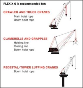
Flex-X® 6

Increased rope stability
Most applications for wire rope are extremely demanding. Wire rope must
resist crushing, bending fatigue, and abrasion. For example, clamshell closing lines must resist bending fatigue and boom hoists are subject to pressures that cause crushing.
Overhead hoists test the stability and strength of a wire rope. All drum-related applications demand a rope that will spool and operate smoothly and dependably.
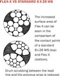
For crane applications where rotation-resistance is not required, Flex-X 6 provides users with superior performance and increased service life in many applications compared to the ropes they had previously employed. When compared to conventional 6 strand ropes, Flex-X 6 ropes provide greater surface area and more steel per given diameter, which increases rope stability and strength, too. This results in longer service life and less sheave and drum wear.
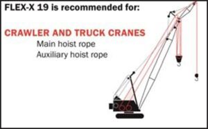
Flex-X® 19

Designed for single or multi-part hoist systems on cranes.
Exclusive Flex-X 19 is designed for use anywhere the rotation-resistant characteristics of a category 2 rotation-
resistant rope are required. Six strands are laid around a core strand in one direction and then 12 strands are laid around this first operation in the opposite direction. Because of its tightly compacted smooth design, Flex-X 19 offers more crushing resistance than standard 9 x 7 rope, higher strength-to-diameter, resistance to bending fatigue, exceptional stability, reduced wear to sheaves and drums, and improved handling, operating, and spooling characteristics.
7-FLEX®
We offer 7-Flex ropes for many applications that currently use 6×19 or 6×36 classification ropes. Their operating characteristics are similar in many ways to 6×36
classification ropes. Typical applications such as container cranes, logging portal cranes and sawmill carriages have reported increased service life with the 7-Flex rope.
The 7-Flex construction offers improved resistance to bending fatigue compared to a 6×26 due to a combination of the outer wire size and the seventh strand.
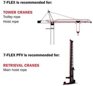
7-FLEX PFV®

Combining the advantages of PFV, a high-grade thermoplastic material, extruded into a 7-Flex lubricated wire rope, provides additional advantages over non-PFV ropes.
On the inside, you’ll find our 7-Flex wire rope that withstands the tough pressures of your demanding jobs while the PFV cushions the strands, distributes internal stresses, keeps in wire rope lubricant and keeps out dirt and debris. PFV also helps shed water and dirt, giving you a clean, smooth surface to make it easy to pass over sheaves and onto drums. This smooth surface works to clean and polish as it extends the service life of your sheaves and drums, while also reducing your cleanup requirements and your maintenance costs.
Minimum Breaking Force and Weights for 7-Flex Ropes
Casar Turboplast®

Casar Eurolift®

Casar Starlift Plus®

Penco® slings are constructed to meet nearly every need. Of course, there are many special situations which require the use of a specialty sling. These are also available. When ordering a specialty sling, be sure to consider:
Ordering Wire Rope Slings
When ordering slings shown in this catalog, the sling number, diameter, and length are required. Unless otherwise specified, the dimensions and fittings indicated will be supplied. When variations are necessary, full dimensions must be specified. For example, alloy oblong links are standard for most bridle slings, and these will be supplied unless otherwise specified. If oblong or pear-shaped carbon links are desired, full link dimensions should be included. In applications where corrosion is a factor, your nearest ALP branch office should be consulted before wire rope is ordered.
Rated Capacities
Rated capacities suggested for ALP slings are based on sound engineering practices and ample design factors, and are in accordance with Occupation Safety and Health Administration standards.
Note:
Rated capacities are only applicable for new slings under normal conditions. As a standard practice to avoid confusion, all angles in this catalog are measured from the horizontal.
Wire Rope Construction
Wire ropes which are regularly used in lifting slings are either 6×19 Class or 6×37 Class. Generally, ropes with diameters up to 1-1/8” inclusive are 6×19 Class and ropes with larger diameters are 6×37 Class. The choice between the two classes may also depend upon the application of the sling, and the characteristics that are most desirable in the sling. For example, if resistance to abrasion is of prime importance, the 6×19 Class is chosen because wires of large diameter provide a high degree
of wear resistance. On the other hand, if flexibility is desired, the 6×37 Class is more satisfactory because of the large number of smaller wires in the rope. Other constructions may be available, but they are rarely used and will not be supplied unless specified.
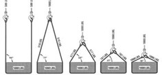
Sling Angle Degrees (A) | Load Angle Factor |
90 | 1.000 |
75 | .966 |
60 | .866 |
45 | .707 |
30 | .500 |
The rated capacity of a multiple leg sling is directly affected by the angle of the sling leg with the horizontal. As this angle decreases, the stress on each leg increases for the same load. If the sling angle is known, the capacity can be readily determined by multiplying the vertical capacity of the sling leg by the appropriate load angle factor from the table above. Then multiply the resulting capacity by the number of legs to the find the assembly’s rated capacity. When more than one angle is involved use the smallest angle for calculating rated capacity.
Wire Rope Sling Inspection
Conditions such as the following should be sufficient reasons for consideration of sling replacement:
Note: All wire rope slings must be tagged and identified by name of manufacturer, diameter or size-rated capacity.
GENERAL NOTES
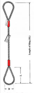
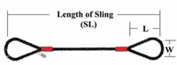
Single Leg Sling w/ Flemish Eyes (Look for the Red Sleeves® )
2 Leg Sling w/ Flemish Eyes (Look for the Red Sleeves®)
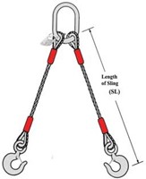
2 Leg Sling w/ Flemish Eyes (Look for the Red Sleeves®)
Note: Sling angles are measured from the horizontal
3 Leg Flemish Eye Sling (Look for the Red Sleeves®)
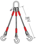
GENERAL NOTES
4 Leg Flemish Eye Sling (Look for the Red Sleeves®)
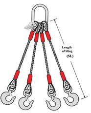
Note: ALP’s policy is to provide safety latches on all assemblies utilizing sling hooks.
Galvanized Cablelaid
Galvanized Cablelaid Flemish Eye Sling
GENERAL NOTES
Note: Sling angles are measured from the horizontal.
6-Part & 8-Part Braided Slings
![]()
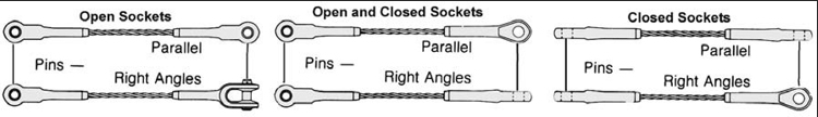
Note: A proper relationship between the socket ends of a pendant is critical to avoid a half-twist in the assembly during installation. Various items are used to describe this relationship.
Top Row: Pins Parallel or Pins in the Plane
Bottom Row: Pins Opposed or Pins in Opposite Planes or Pins at Right Angles
We are now part of MHI-CMAA (Crane Manufacturers Association Of America, Inc.)


